Optical module validation connects component performance with the behavior of a complete transmitter or receiver under realistic interfaces. They need to reproduce the intended data rate, modulation format, laser condition, fiber path, electrical drive, temperature, and control behavior.
Equipment selection is therefore an architecture decision, not a shopping list based on a headline specification. A useful setup must expose enough information to diagnose failure. If a module misses an eye or error target, they should be able to separate driver loss, modulator response, laser power, bias drift, connector loss, detector limitations, and firmware behavior.
Integrated equipment can simplify connections, but it must still provide observable states and defined reference planes. Validation coverage is linked to customer use conditions and applicable standards, preventing excessive testing in irrelevant areas while leaving material operating corners unexamined.
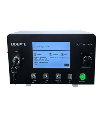
For module work, available fiber optic test equipment includes an EO transmitter with 40, 70, or 110 GHz options, a dedicated bias controller, and a narrow-linewidth laser. They evaluate these functions against the module roadmap, then add calibrated RF paths, receivers, thermal control, automation, and data management required for qualification evidence.
Validation Requirements Should Be Derived from the Module Architecture
The required fiber optic test equipment depends on whether the module uses direct detection, coherent modulation, or a sensing waveform. Direct links need representative intensity drive and receiver bandwidth; coherent modules add phase, polarization, local-oscillator, and DSP considerations.
They write a validation matrix covering nominal operation, margin tests, environmental extremes, restart, and fault response. Optical test equipment must also support the module optical budget. Source power, wavelength, linewidth, relative intensity noise, attenuation range, and monitoring accuracy affect results.
They identify which source characteristics belong to the product and which are imposed by the bench, then include reference measurements that prevent source drift from being mistaken for module variation. Electrical interfaces deserve equivalent detail.
Cables, adapters, fixtures, and board launches may consume significant bandwidth at high rates. They characterize them with appropriate calibration and preserve raw correction data. The validation report states the electrical and optical reference planes so that supplier, customer, and internal results can be compared without hidden assumptions.
Bandwidth and Source Quality Must Match the Intended Signal
At the signal-generation stage, an EO transmitter configured for the target frequency range can serve as fiber optic test equipment by integrating a DFB source, monitors, attenuation, and bias stabilization. They choose 40, 70, or 110 GHz based on waveform content and required margin, not simply the module name.
Excess capability adds cost if the fixture or detector remains limiting. For optical test equipment supporting coherent or chirped modules, a stable source may be important. The listed narrow-linewidth single-frequency laser provides a 1551.4 nm center wavelength, 8 dBm output, intrinsic linewidth of 200 Hz or less, chirp bandwidth above 8.2 GHz, and chirp linearity above 0.9993.
They verify tuning, warm-up, noise, trigger behavior, and compatibility with their receiver architecture. During extended sequences, automatic bias control can stabilize the output, but validation should test both controlled performance and underlying device demand. They log correction voltage, lock status, recovery time, and response to optical-power or temperature changes.
This exposes whether the module has comfortable bias margin or relies on continuous compensation near the limit of the controller range. They maintain known-fault modules for periodic station challenges, verifying that software and hardware changes have not reduced the setup’s ability to identify real defects.
Automation and Correlation Determine Whether the Setup Can Scale
Scalable fiber optic test equipment requires remote commands, deterministic timing, data export, self-checks, and error handling. They build automation around documented instrument states and preserve configuration with every result.
Scripts are challenged with resets, interrupted runs, invalid settings, and software upgrades before they are accepted for qualification or transferred to production. Correlation among optical test equipment stations uses multiple reference modules across the performance range. Repeated measurements show bias, reproducibility, and sensitivity to reconnection.
They define allowable differences and investigate systematic offsets before combining data. A single reference module may confirm continuity, but it cannot establish correlation across loss, power, and bandwidth ranges. Support and calibration complete the selection.
They review turnaround time, service locations, loaner policy, firmware control, spare connectors, and change notification. Module schedules can be disrupted by unavailable measurement infrastructure. Lifecycle cost therefore includes expected maintenance and the technical effort required to keep results comparable through several product generations.
Capital planning includes expected utilization and upgrade paths, allowing one platform to support several module generations without purchasing bandwidth that will remain unused. Optical module validation needs a test system that recreates the intended signal, controls important variables, and leaves enough visibility for root-cause analysis.
The correct equipment specification follows from module architecture and acceptance decisions. More bandwidth or integration is useful when it improves measurement confidence and reduces uncertainty in the final product result.
Their approval process includes representative modules, environmental operation, margin testing, station correlation, automation stress tests, and calibration review. They also confirm that results can be translated into design actions or production limits. A setup that generates polished plots but cannot isolate failures or support traceable records is not ready for program use.
Validation equipment is useful when it reproduces realistic impairments and leaves a traceable record behind. Correlation and throughput trials can show how Liobate functions contribute to calibration, automation, and production decisions.
